
What this topic is
A microcontroller is a small computer on one chip. It reads its inputs, follows a program and switches its outputs.
You plan the program as a flowchart, read it as numbered lines the way the exam prints it, then build it on an Arduino Uno and test it.
Slides and resources
Every lesson's slides, with and without answers.
Microcontrollers Exam
A microcontroller is a small, programmable chip that controls a system. It runs a program stored in its memory. It reads inputs and switches outputs.
In the exam Advantages over hard-wired control, and wiring a microcontroller. 2021 Q7(b) · 2022 Q14(c) · 2023 Q9(d) · 2025 Q8(c) · 2026 Q13(e)
The exam's microcontroller
- 8 pins: each one is an input or an output.
- The I/O table in the question says which.
- In our room: inputs on pins 2 and 3, outputs on pins 4 to 7.
Input (a switch or a sensor) → process (the microcontroller and its program) → output (a lamp, buzzer or motor).
Where you meet one
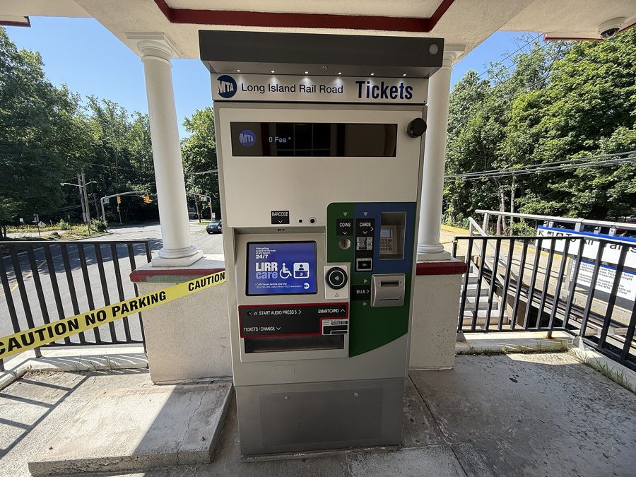
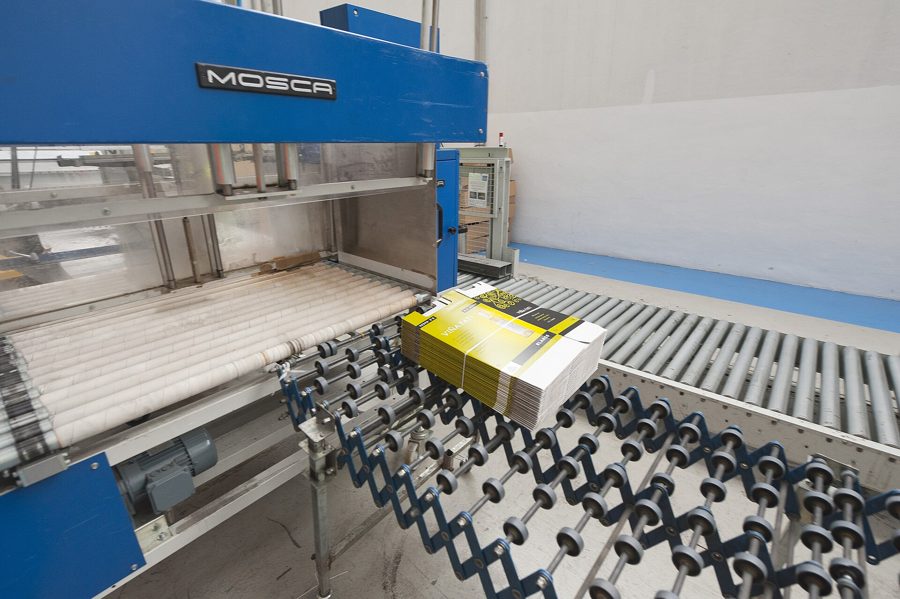
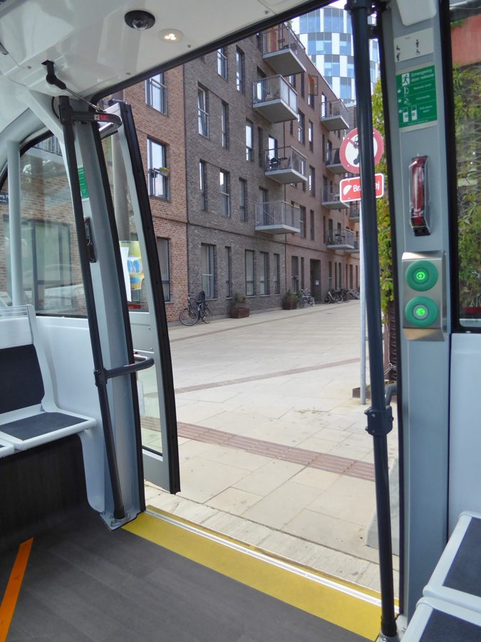
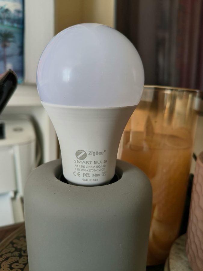
The booklet sorts examples into sectors. One of each:
Hard-wired or programmable?
| Hard-wired | Programmable | |
|---|---|---|
| Made of | fixed components and wires | a microcontroller and a program |
| The job is | in the wiring | in the program |
| To change the job | new parts, new wiring | change the program |
Advantages and disadvantages
| Advantage | Why |
|---|---|
| Reprogrammed | change the program, not the wiring |
| Re-used | one board, many products |
| Fewer components | so more reliable, and faster to assemble |
| Disadvantage | Why |
|---|---|
| Needs a programmer | someone must write and test the program |
| Needs a power supply | the chip needs one to run |
| Harder to follow | you cannot see the job by looking at the parts |
Model answer
Describe two advantages of a microcontroller over a hard-wired circuit for a bus's doors. 2 marks
Wiring inputs and outputs
- Input: a switch from 5 V to the pin. Pressed, the pin gets 5 V and the program reads it as on.
- Output: from the pin to 0 V. Switched on, the pin gives 5 V, current flows and the buzzer sounds.
- A motor needs a transistor. A pin gives a small current, about 20 mA. A motor needs much more.
The transistor driver: the base lead goes pin → resistor → base. The collector has the motor, with a diode across it. The emitter goes to 0 V.
Watch out: "driver" on its own scores 0. Say it is a transistor.
1. Describe two advantages of using a microcontroller rather than a hard-wired circuit to control a lift. 2 marks
Answer
2. Explain why a microcontroller is used in an automatic washing machine. 2 marks
Answer
3. State why a transistor is connected between pin 7 and a motor. 1 mark
Answer
Flowcharts Exam Assignment
A flowchart shows the steps of a program in order, using the six symbols in the data booklet. The exam asks you to complete a flowchart from an I/O table every year.
In the exam Completing a flowchart from an I/O table: every paper. 2021 Q13(b) · 2022 Q9(a) · 2023 Q8(a) · 2024 Q11(b)
The six symbols
All six are on page 6 of the data booklet.
| Symbol | Name | Its job |
|---|---|---|
| Terminator | Start or end of a program or sub-procedure. | |
| Line | The direction of flow. Arrows are needed going up or left. | |
| Input / output | Switches an output, or reads an input. Give the pin. | |
| Process | An operation, for example a delay. Give the unit. | |
| Decision | A yes or no question. Label the paths Y and N. | |
| Sub-procedure | Runs a separate section of program, then comes back. |
Lines and arrows
- Down or right: an arrow is not needed.
- Up or left: an arrow is needed.
- Every loop back: draw its arrow. The marking instructions mark it.
What goes in the box
| Box | The exam's way |
|---|---|
| Output | pin 7 on · pin 7 off |
| Input decision | pin 1 on? |
| Delay | pause 0.5 s (always a unit) |
| Fixed loop | x3? |
The booklet writes the same boxes as Lamp (output, pin 13) ON, Wait 1 s (1000 ms) and count < 5?. Both score. Either way, every output has its pin and every delay has its unit.
The four structures
Continuous loop
Repeats for ever, until the power goes off. Drawn as a line back up, with an arrow.
Fixed loop
Repeats a set number of times, then moves on. Drawn as a decision, x3?, with N looping back.
Time delay
The program waits for a set time. Outputs stay as they are while it waits.
Branch
A yes or no decision. Each answer has its own path, labelled Y and N.
How the marks are given
- Each output: on and off, in the right place (1)
- Each input decision: Y, N, a loop and an arrow (1)
- Each delay: right place, with a unit (1)
- x3?: Y, N, and an arrow back before the repeat (1)
- A loop to the start with an arrow, or an end (1)
- All the symbols right (1)
The method
- Read the I/O table: which pins are in, which are out.
- Draw one box per bullet, in order, top to bottom.
- Turn each input into a decision, pin 1 on?, with Y and N.
- Turn each repeat into x3?, with an arrow back.
- Finish: loop to the start, or end. Check pins, units and arrows.
Worked example. Input: train sensor, pin 0. Outputs: lamps, pin 7; barrier motor, pin 6. When the train sensor is on, the lamps flash 4 times, 0.5 s on and 0.5 s off. The barrier motor then turns on for 6 s, then off. The sequence returns to the start. 9 marks
Answer
pin 0 on?: Y, N, loop (1) · pin 7 on, off (1) · both pauses with units (1) · x4?: Y, N (1) · arrow back (1) · pin 6 on, off (1) · pause 6 s with unit (1) · loop to start (1) · all symbols right (1).
Build it in a simulator
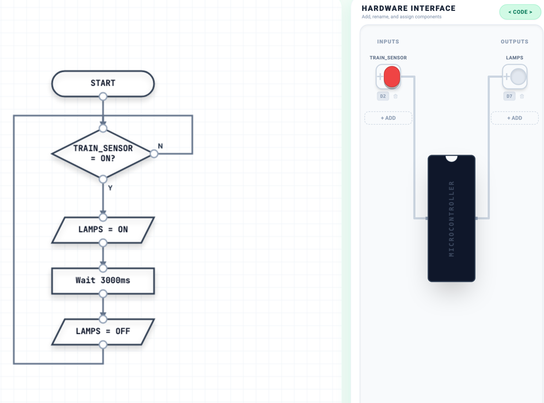
NoSyntaxSim draws the same symbols. Each input or output box picks a pin from the hardware panel. Run Programme lights each box as it runs. It writes a delay as Wait 3000ms; on paper we still write pause 3 s.
Yenka builds the same flowchart with its own symbols. In class you use both, so you know both.
1. A car wash has a button on pin 1, a pump on pin 5 and a brush on pin 4. When the button is pressed, the pump runs for 20 s, then stops; the brush then runs for 30 s, then stops. The sequence repeats. Complete the flowchart. 6 marks
Answer
pin 1 on? with Y, N, loop and arrow (1) · pin 5 on and off (1) · pin 4 on and off (1) · both pauses with units (1) · loop to the start with an arrow (1) · symbols (1).
2. State the programming structure: a sign flashes all day. 1 mark
Answer
3. State the programming structure: a bell rings 4 times, then stops. 1 mark
Answer
Reading programs Exam
The exam prints a program as numbered lines. Each line is one box of a flowchart. You will be asked to read it: find a line, count the loops, say what a line does. You are never asked to write code.
In the exam Reading a program: 3 of the last 6 papers. 2022 Q9(b)(c) · 2023 Q9(c) · 2025 Q2
The words the exam uses
| In the program | It means |
|---|---|
| switch on 6 | pin 6 on |
| pause 4000 | wait 4000 ms = 4 s |
| main: label_1: | a name for a line |
| goto main | jump to that line |
| if … then main | a decision |
| let count = … | a counter |
pause is in milliseconds. 1000 ms is 1 s. The flowchart writes the same step as pause 4 s.
- main:if input1 is off then main
- switch on 6
- pause 4000
- switch off 6
- goto main
Counting: the fixed loop
The flowchart's x4? becomes three lines:
- line 1 sets the count to 0,
- line 6 adds 1 each time round,
- line 7 checks it.
Line 8 jumps back to label_1, which is below line 1. So the count is not reset, and the buzzer beeps 4 times.
- main:let count = 0
- label_1:switch on 5
- pause 200
- switch off 5
- pause 200
- let count = count + 1
- if count = 4 then label_2
- goto label_1
- label_2:end
Model answers
Describe the function of line 5 in the barrier program. 1 mark
Scores 0: "It goes to main." Say what that does.
Marking instructions, 2022 Q9(b).
- main:if input1 is off then main
- switch on 6
- pause 4000
- switch off 6
- goto main
Explain why lines 2 to 7 do not run 10 times. 2 marks
The word so joins the cause to its effect.
Marking instructions, 2022 Q9(c).
- main:let count = 0
- label_1:switch on 7
- pause 300
- switch off 7
- pause 300
- let count = count + 1
- if count = 10 then label_2
- goto main
- label_2:switch on 5
- end
Your turn: program to flowchart
Draw the flowchart for this program on paper. Check every pin, every unit and every arrow. Then open the answer.
- main:if input3 is off then main
- switch on 5
- switch on 4
- pause 2000
- switch off 5
- pause 1000
- switch off 4
- goto main
Answer
Three ways to write one program
The same buzzer program, written the exam's way, the booklet's way and in Arduino C. Watch the times: the exam's pause 500 and Arduino's delay(500) are milliseconds. The booklet says 0.5 seconds.
The exam
main:
switch on 5
pause 500
switch off 5
pause 1000
goto main
The booklet
loop
high buzzer
pause 0.5 seconds
low buzzer
pause 1 second
end loop
Arduino C
void loop() {
  digitalWrite(5, HIGH);
  delay(500);
  digitalWrite(5, LOW);
  delay(1000);
}A car wash brush is controlled by this program.
- main:if input2 is off then main
- let count = 0
- label_1:switch on 6
- pause 3000
- switch off 6
- let count = count + 1
- if count = 4 then main
- goto label_1
1. State the line number that contains a time delay. 1 mark
Answer
2. State how many times pin 6 switches on each time input 2 comes on. 1 mark
Answer
3. State the type of loop in lines 3 to 8. 1 mark
Answer
4. Line 8 is changed to goto main. Explain what happens to the brush. 2 marks
Answer
Build, test and fix Assignment
On the Uno, the plan becomes real: NoSyntaxSim → Duino.app: Verify → Upload → build it. Then you test every job, fix what fails, and test again. The assignment asks for exactly this.
Pins The exam uses inputs on pins 0–3 and outputs on 4–7. Our Uno uses inputs 2–3 (pins 0 and 1 carry its USB link) and outputs 4–7. The booklet's code uses pins 13, 9–11 and 8.
Getting started on the Uno
Our boards are Elegoo Uno R3, a copy of the Arduino Uno. You program them in Duino.app.
- Open Google Chrome (or Edge) and go to duino.app. Safari and Firefox can't reach the USB port.
- Plug the board in with its USB cable. A light on the board comes on.
- Choose the board Arduino Uno. Check it every lesson: the wrong board means the upload fails.
- The first time you upload, Chrome asks which USB device to use. Pick the one that names Arduino, CH340 or USB Serial, then Connect.
- In the Code tab, delete the code that is already there, then type yours.
Verify before you Upload, every time. Verify (some versions say Compile) checks your spelling and punctuation without touching the board. Upload sends the program to the board and runs it. If Verify shows an error, it names the line: fix it first.
Anything after // is a note for people. The board ignores it. Delete the code and the board stops working; delete the notes and it works the same, but no one can follow it. Add your own notes to explain your thinking.
- Row 3, holes a–e: joined to each other.
- Row 3, holes f–j: joined to each other, but not to a–e.
- The + rail: joined all the way down. So is the − rail.
- The centre gap (blank strip) is not joined across.
LEDs and buzzers on the breadboard
- Every LED needs a 220 Ω resistor in series. Without one, too much current burns out the LED, and can damage the pin.
- The LED's long leg (+) goes towards the Uno's pin. The short leg, by the flat edge, goes through the resistor to GND.
- An LED works only one way round. If it won't light, turn it round.
- A resistor has no + or −. 220 Ω is red, red, brown, then gold.
- A buzzer needs no resistor. Its + leg (marked +, longer) goes to the pin.
It won't upload, or it won't work
| What happens | Check this |
|---|---|
| Upload fails, or "no board" | Arduino Uno chosen? USB plugged in? Did you press Connect when Chrome asked? |
| Red error on Verify | Read the line number. Usually a missing ; or a misspelled word. |
| Uploaded, but nothing happens | Did you press Upload, or only Verify? Verify only checks. |
| Nothing on the breadboard works | 5V to the + rail and GND to the − rail? Legs in the same row, on the same side of the gap? |
| One LED won't light | Long leg towards the pin? Its resistor reaching GND? Try it the other way round. |
The buzzer only clicks with tone() | It is an active buzzer: switch it with digitalWrite instead. |
Worked example 1: the flashing lamp
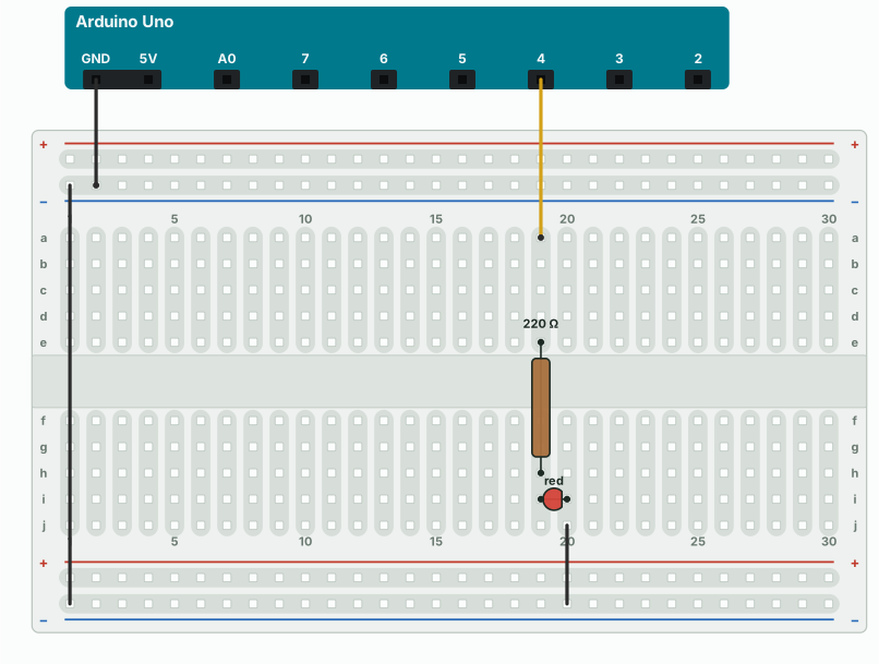
A warning lamp flashes on and off the whole time the machine is on.
void setup() {
  pinMode(4, OUTPUT);
}
void loop() {
  digitalWrite(4, HIGH);
  delay(1000);
  digitalWrite(4, LOW);
  delay(1000);
}
setup() runs once: pin 4 is an output. Everything in loop() repeats for ever: that is the continuous loop. delay(1000) holds the lamp for 1000 ms, 1 s.
Worked example 2: traffic lights
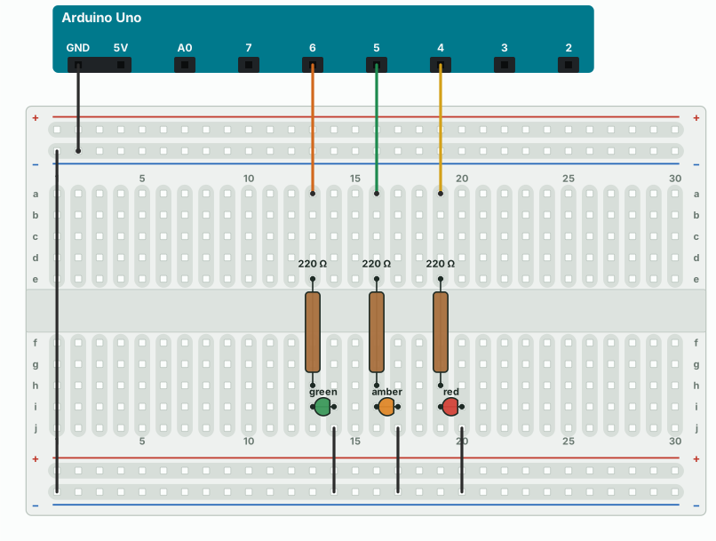
The UK sequence: red; red and amber; green; amber; back to red. Red on 4, amber on 5, green on 6.
void setup() {
  pinMode(4, OUTPUT);   // red
  pinMode(5, OUTPUT);   // amber
  pinMode(6, OUTPUT);   // green
}
void loop() {
  digitalWrite(4, HIGH);
  delay(3000);
  digitalWrite(5, HIGH);
  delay(1000);
  digitalWrite(4, LOW);
  digitalWrite(5, LOW);
  digitalWrite(6, HIGH);
  delay(3000);
  digitalWrite(6, LOW);
  digitalWrite(5, HIGH);
  delay(1000);
  digitalWrite(5, LOW);
}
Three outputs, so three pinMode lines, and each LED has its own 220 Ω. Two outputs HIGH at once give the red and amber stage.
Worked example 3: the darkness alarm
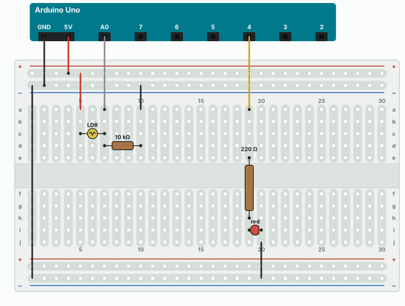
When it gets dark, the LED flashes 5 times, then the system keeps watching.
void setup() {
  pinMode(4, OUTPUT);
  // A0 is an analogue input: no pinMode
}
void loop() {
  int light = analogRead(A0);
  if (light < 300) {
    for (int i = 0; i < 5; i++) {
      digitalWrite(4, HIGH);
      delay(500);
      digitalWrite(4, LOW);
      delay(500);
    }
  }
}
analogRead(A0) gives a number from 0 to 1023. In the dark the LDR's resistance goes up, so A0 goes down. if (light < 300) is the branch. for (i = 0; i < 5; i++) is the fixed loop: i counts 0, 1, 2, 3, 4, which is five flashes.
Find and fix
Finding faults is called debugging. Change one thing at a time, then test again: change two things and you will not know which one fixed it.
- What should it do?
- What does it do?
- Which line?
- Change one thing.
- Test it again.
Debug build 1 should flash pin 4, 1 s on and 1 s off. It has 2 faults.
void setup() {
}
void loop() {
  digitalWrite(4, HIGH);
  delay(1);
  digitalWrite(4, LOW);
  delay(1000);
}
The faults
Debug build 2 should sound the buzzer on pin 7 for 2 s when the button on pin 2 is pressed. It has 2 faults.
void setup() {
  pinMode(2, INPUT);
  pinMode(7, OUTPUT);
}
void loop() {
  if (digitalRead(2) = HIGH) {
    digitalWrite(7, HIGH);
    delay(2000);
    digitalWrite(7, LOW);
  }
The faults
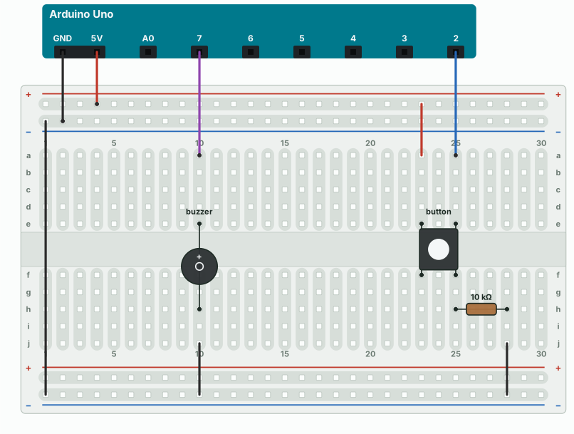
Test, amend, re-test
A pedestrian crossing: red until the button is pressed; then green and the beeper for 5 s; then back to red. One test for each job:
| Test | Should happen | Initial result | Planned amendment | Re-test |
|---|---|---|---|---|
| Press | red off, green on | red off, green on | none | |
| Wait 5 s | green off, red on | green off, red on | none | |
| Beeper | stops after 5 s | stays on | add pin 7 off | stops: pass |
Say what you saw, by part. "It didn't work" names no part and no result. "The beeper stayed on after 5 s" does.
Final version. After the re-test, save it under a new name. The assignment asks for the final version.
Model answer
Suggest one improvement to the crossing. Justify it. 2 marks
"Make it better" scores 0: it names no improvement and gives no reason.
Practical sheets and the sim file
To open the crossing, press Load Flowchart in NoSyntaxSim and choose the file.
Check your booklet work
Answers to Booklet 4b. Try each one first, then open it. The booklet's own pins (13, 8) are kept here, because the questions use them.
Task 1 — Microcontrollers in use (page 3)
| Product | Why a microcontroller suits it (any valid reason) |
|---|---|
| Microwave oven | Runs a timed sequence; reads the door switch and buttons; switches the heater, motor and lamp from one chip. |
| Traffic lights | A repeating timed sequence; the timings change by editing the program, not rewiring. |
| Robot arm in a factory | Controls several motors in order from sensor inputs; reprogrammed for a new task. |
| Smart heating thermostat | Reads a temperature sensor, decides, follows a time schedule; settings change in the program. |
Practice — Programming structures (page 7)
- A continuous loop repeats for ever, until the power is removed.
- A fixed loop repeats a set number of times, then the program carries on.
- A time delay pauses the program for a set time; the outputs stay as they are.
- A branch makes a yes or no decision, so the program follows one of two paths.
- A fixed loop (6 repeats).
- A continuous loop, with a branch inside it to test the sensor.
Practice — Flowcharts (pages 9 to 13)
- The missing process box: Wait 4 s (4000 ms).
- Wait 5 s (5000 ms); Wait 2 s (2000 ms); Buzzer (output, pin 8) OFF.
- LED (output, pin 13) ON; Wait 1 s; LED (output, pin 13) OFF; Wait 1 s. The question gives no pin: any pin scores, the same one on and off.
- The decision Pressed? (No loops back); Buzzer (output, pin 8) ON for 2 s (2000 ms); Buzzer (output, pin 8) OFF.
- count = 0; LED ON; Wait 0.5 s; LED OFF; Wait 0.5 s; count = count + 1; the decision count < 5? (Yes loops back, No goes to Stop).
Worked examples — Try changing this (pages 15 to 19)
Worked example 1. (1) Both delays 200: it flashes faster: 0.4 s a flash, so 2.5 times a second. (2) 100 on, 900 off: a short blink once a second. (3) The board only drives the pin named in the code, so pinMode, digitalWrite and the wire must all use the same pin.
Worked example 2. (1) Change the delay after green comes on: delay(3000) becomes delay(6000). (2) Yes, it still runs: // starts a comment, which the board ignores. (3) Nothing goes wrong: setup() still makes all three pins outputs. Swap the pins in the digitalWrite lines instead and the colours change places.
Worked example 3. (1) 300 to 600: it triggers more easily; it counts as dark at a brighter light level. (2) i < 10: the LED flashes 10 times. (3) < swapped for >: the alarm goes off in the light, not the dark.
Find and fix (pages 20 and 21)
Debug build 1. setup() has no pinMode(13, OUTPUT);. delay(1) should be delay(1000).
Debug build 2. digitalRead(2) = HIGH should be == HIGH. loop() is missing its closing }.
Practice — Programming in real life (pages 22 and 23)
- setup() runs once when the board starts; it sets which pins are inputs and outputs.
- loop() runs over and over, for ever, after setup(); it holds the main control program.
- digitalWrite(13, HIGH);
- pinMode(4, INPUT);
- 2.5 s (2500 ms).
- (4 marks) for count = 1 to 4 / high LED / pause 0.5 seconds / low LED / pause 0.5 seconds / next count / end. Repeats 4 times (1); LED on (1); LED off (1); both pauses 0.5 s with a unit, then end (1).
- (4 marks) setup(): pinMode(2, INPUT); pinMode(8, OUTPUT); loop(): if (digitalRead(2) == HIGH) { digitalWrite(8, HIGH); delay(3000); digitalWrite(8, LOW); }. Both pinMode lines (1); inside loop() so it repeats (1); if with digitalRead(2) (1); buzzer on, delay(3000), buzzer off (1).
- (4 marks) The question gives no pin: use any pin, the same in all three lines. setup(): pinMode(13, OUTPUT); loop(): digitalWrite(13, HIGH); delay(1000); digitalWrite(13, LOW); delay(1000); pinMode in setup (1); code inside loop() (1); HIGH then LOW (1); both delays 1000 (1).
Check yourself
Rate your confidence: the booklet's success criteria
R not yet, A getting there, G confident. Saved on this device only.
Recap and words
What loses marks
- "Easier to change", "cheaper", "programmable" or "fewer components" on their own.
- An output box with no pin: write pin 4 on, not "lamp on".
- A delay with no unit: write pause 4 s.
- A loop back with no arrow, or a decision with no Y and N.
- "Goes to main" on its own: say what that does.
- An explain answer with a cause but no effect: join them with so.
- Answering a programmable control question in Arduino C.
- "Driver" on its own: say it is a transistor, and why.
Glossary
- Microcontroller
- A small, programmable chip that controls a system.
- Input / output
- A box that reads an input or switches an output. Give the pin.
- Process
- A box for an operation, such as a delay. Give the unit.
- Decision
- A yes or no question. Its paths are labelled Y and N.
- Terminator
- Start or end of a program.
- Sub-procedure
- Runs a separate section of program, then comes back.
- Continuous loop
- Repeats for ever: a line back up, with an arrow.
- Fixed loop
- Repeats a set number of times: a decision such as x3?.
- Label
- A name for a line, such as main: or label_1:, so goto can jump there.
- Arduino C
- The code the Uno runs: setup() once, then loop() for ever.
- Transistor driver
- Lets a pin's small current switch a motor's large current.
- Debugging
- Finding and fixing faults: change one thing, then test again.
Where this comes up next
Sources & credits: the text, programs, flowcharts, wiring and breadboard drawings are by R Stewart, written for Booklet 4b. Past paper references, marking instruction wording and the course specification © Qualifications Scotland (SQA). Photos via Wikimedia Commons: Infrastorian (CC0), SimónK (CC BY-SA 4.0), Leif Jørgensen (CC BY-SA 4.0), Danielrosehill (CC BY 4.0). NoSyntaxSim V2 by Peter Strain (NoStrainSims). R Stewart - October 2026.