The magnetic effect of a current and the electromechanical devices it
drives (incl. the relay and flyback diode), then the component symbols you must know.
Concept 1
Magnetic effect & electromechanical devices
Key words
Coil
wire wound round and round; it makes a magnetic field.
Relay
a coil-worked switch for a separate, bigger circuit.
Back-EMF
a sudden burst of voltage when a coil is switched off.
Flyback diode
a diode that lets the back-EMF flow away safely.
A current in a wire creates a magnetic field around it. The field is stronger when the wire is wound into a coil (and stronger still with an iron core).
This drives electromechanical devices — each turns a current into movement or sound using a coil's magnetic field:
Relay — the coil's field pulls a switch contact, so a small signal switches a separate, larger circuit (and keeps the two circuits isolated).
Solenoid — the coil pulls an iron core/armature in a straight line (e.g. a lock or valve).
Motor — the coil's field reacts with magnets to spin the shaft, giving rotation.
Buzzer — the coil vibrates a part rapidly to make a sound.
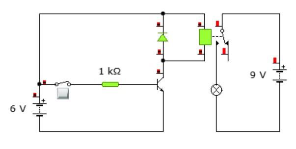
Back-EMF: when you switch the coil off, it makes a sudden burst of voltage (called back-EMF). This burst can damage the transistor. A flyback diode is fitted the "wrong" way (in reverse bias) across the coil: it normally blocks current, but it lets this burst flow away safely.
A small input switches the transistor on, energising the relay coil; the coil pulls the contacts closed and switches on the lamp in a separate circuit. The flyback diode (reverse-biased across the coil) safely conducts the back-EMF and protects the transistor.
✍️ How to say it
The diode is fitted in
across the relay coil.
When the coil switches off it makes a sudden burst of voltage called
.
The diode lets this flow away safely, so it does not damage the
.
See a full answer
The diode is fitted in reverse bias across the relay coil. When the coil switches off it makes a sudden burst of voltage (back-EMF). The diode lets this flow away safely, so it does not damage the transistor.
Practice 1
State why a flyback diode is connected across a relay coil, and explain why it must be fitted in reverse bias.
Answer
It protects the switching transistor from the large reverse voltage (back-EMF) produced when the coil's magnetic field collapses. In reverse bias it does not conduct during normal operation, but it conducts the back-EMF safely back round the coil when the current is switched off.
✅ You can now…
name what a relay, solenoid, motor and buzzer do.
explain why a flyback diode is fitted across a relay coil.
Concept 2
Component symbols & functions
Key words
Symbol
the drawing that stands for a component.
Function
the job the component does in the circuit.
LDR
a resistor whose resistance falls as light rises.
Thermistor
a resistor whose resistance changes with heat.
You must draw, identify and describe the function of
each component below. These pages use the UK / IEC rectangle form for resistors (the same
convention as the Higher Physics pages); logic gates use their distinctive shapes (see Logic gates & ICs).
Cell / battery
supplies energy — provides the p.d.
Resistor
limits the current
Variable resistor
resistance you can adjust
LDR
resistance falls as light rises
Thermistor
resistance changes with temperature
Diode
lets current flow one way only
LED
emits light when forward biased
Capacitor
stores charge (non-electrolytic)
Electrolytic cap.
polarised — mind the + lead
Transistor (NPN)
electronic switch / amplifier
MOSFET (n-channel)
voltage-controlled switch
741 op-amp
comparator — compares two voltages
Switch
makes or breaks the circuit
Relay
coil switches a separate circuit
Motor
turns electrical energy into rotation
Buzzer
sound output
Lamp
light output (filament)
Solenoid
coil pulls an iron core / armature
Speaker
converts a signal to sound
Fuse
breaks if the current is too high
Volt- / ammeter
V in parallel, A in series
All symbols here follow the UK (BS) convention — resistors are drawn as
a plain rectangle, the same as on the SQA question paper and data sheet. The logic-gate
symbols are in Logic gates & ICs,
and the 741 / 555 / 7400-series IC pin-outs are in
the same topic's pin-out reference.
Practice 2
In an exam a pupil writes that a cell "gives power" to a circuit. Give a better answer for what a cell does, and name the component whose resistance falls as light increases.
Answer
A cell supplies energy — it provides the p.d. (voltage) that drives the current. The component whose resistance falls as light rises is the LDR (light-dependent resistor).
✅ You can now…
draw and identify the components on the SQA list.
recognise each component from its UK (BS) symbol on a circuit diagram.
Interactive
Component Collector quiz
Name the component from its UK (BS) symbol. Ten symbols are drawn from
the reference grid above — get 8 / 10 to earn the 🔌 Component Collector
badge.
Name the symbol scored
Pick the component each symbol represents, then check your answers.