S3 Physics – Electricity 2: Electronics and Control
Overview
In Electricity 2 we move from “just circuits” to electronics and control. You’ll learn how a potential divider can turn changes in light or temperature into a useful output, how to power an LED safely, and how a circuit can switch at the right moment.
The same ideas keep coming back: resistance changes → voltages change → output changes. By the end of this unit, you’ll be reading the hidden language of control circuits — using diagrams, measurements, and real builds you can test.
🔗 Key links
Start with the Knowledge Organiser (symbols + rules), then use your booklet.
🧠 Knowledge Organiser (B2) MAIN
Symbols, divider rules, tools/testing box — start here.
📘 Electricity 2 Booklet (B2) practice
Do sections, get checked, then move on.
⚡ Physics Past Paper Finder mixed Qs
Use after KO + methods (not just calculations).
💡 Electronics PPQ Section C
Great for symbols, switching, simulation, safety & tools.
✅ What to attempt (tap to open)tap to open
- Physics: focus on Voltage, Ohm’s Law, Circuit rules.
- Electronics: symbols & functions, resistor values, series/parallel, switching circuits, voltage dividers, simulation/testing, safety, errors, layout/diagrams.
- Note: you may see a few unfamiliar symbols (mix of S3 + N5 Electronics).
▶ Video revision (watch only what you need)
Open a video to load it. Watch → then go straight to booklet questions.
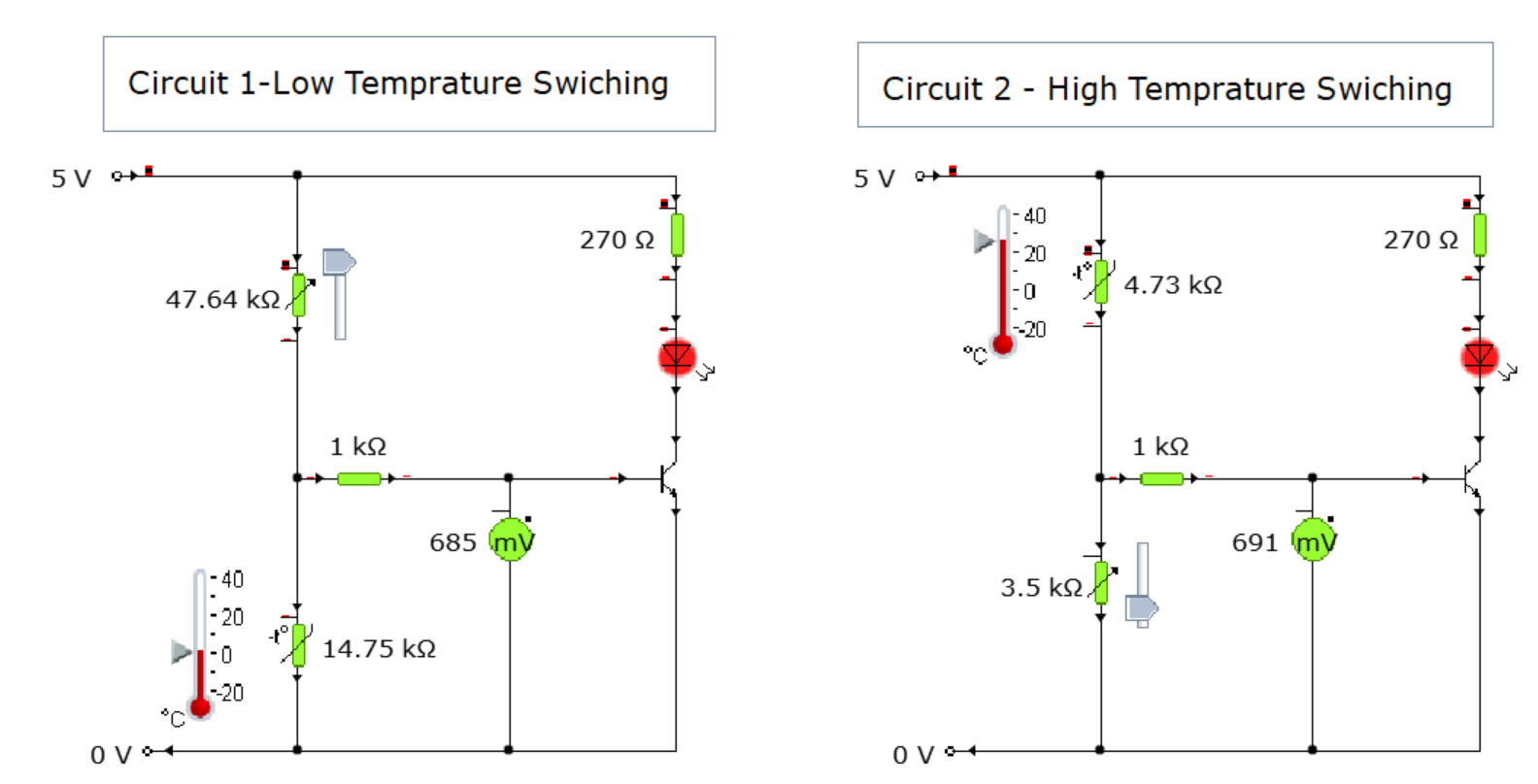
Voltage Divider Theorytap to load
Voltage Divider Theory
How changing resistor values changes the output voltage.
LEDs – Basictap to load
LEDs – Basic
Why LEDs need a protective resistor.
Thermistors and LDRstap to load
Thermistors and LDRs
How sensors change resistance.
Transistor Switching Circuitstap to load
Transistor Switching Circuits
Using a transistor as a switch.
Stripboard Schematicstap to load
Stripboard Schematics
Plan track cuts and links before soldering.
🧾 Test details (no spoilers)
What to expect
- 3 sections in total.
- Section 1: 5 multiple choice questions.
- Section 2: Physics written questions — 15 marks.
- Section 3: Electronics written questions — 10 marks.
- Total time: 45 minutes.
Time strategy
- Do the easy marks first (build confidence).
- If stuck: write what you do know (often earns marks).
- Leave ~5 minutes at the end to check units, polarity and sensible answers.
🎯 Success criteria (G / A / R) — saved on this device
Tap each statement and choose G, A or R. Use the summary to decide what to do next.
💡 LED tool (protective resistor ↔ current)
Use this to either: (1) calculate the protective resistor for an LED, or (2) calculate the current if you already know the resistor.
🎯 LED practice (random + check your answer)tap to open
Try working it out yourself first, then check. (We accept ±5%.)
🎛️ Switching circuits (transistor + MOSFET)
Use the sentence builder to practise the exact cause → effect style the marking instructions reward.
✅ Switching sentence builder (SQA-friendly)tap to open
⭐ Quick science remindertap to open
- LDR: more light → lower resistance.
- NTC thermistor: higher temperature → lower resistance.
- Exam wording: say Vout at the junction (base/gate voltage) changes — that’s what the transistor/MOSFET “sees”.
- Voltage word: BJT uses switching voltage; MOSFET uses threshold voltage.
🧾 Copy-paste model answers (SQA style)tap to open
3-mark template (switch ON)
- When [condition] [increases/decreases], the resistance of the [LDR/thermistor] [decreases/increases].
- This means Vout (output voltage at the junction / base (or gate) voltage) [increases/decreases].
- When Vout reaches the switching voltage (BJT) / threshold voltage (MOSFET), the transistor/MOSFET switches on, so the [LED/motor/relay] switches on.
If relay present: “the relay coil is energised and the contacts close, switching on the device.”
3-mark template (switch OFF)
- When [condition] [increases/decreases], the resistance of the [LDR/thermistor] [decreases/increases].
- This means Vout (output voltage at the junction / base (or gate) voltage) [increases/decreases].
- When Vout falls below the switching voltage (BJT) / threshold voltage (MOSFET), the transistor/MOSFET switches off, so the [LED/motor/relay] switches off.
If relay present: “the relay coil is de-energised and the contacts open, switching off the device.”
Do / Don’t (mark-friendly wording)
- ✅ Do say: “Vout at the junction (base/gate voltage) increases/decreases.”
- ✅ Do say: “When Vout reaches the switching/threshold voltage → switches on.”
- ✅ Do say (relay): energised/de-energised; contacts close/open.
- ❌ Don’t say: “voltage through the resistor/sensor”
- ❌ Don’t rely on: “current increases so it turns on” unless asked about current.
🧯 Soldering guide + checklist (saved on this device)
Use this before you build on PCB or stripboard. Tick items as you go — ticks are saved on this device.
✅ Open the soldering checklisttap to open
1) Safety + setup (before you start)must-do
2) Soldering technique (perfect joints)how-to
What you do (every joint)
- Heat the joint: tip touches pad/track + component lead together.
- Feed solder to the joint (not to the iron).
- Remove solder first, then remove the iron.
- Keep it still for a few seconds while it cools.
What it should look like
- Shiny joint.
- Small “volcano” shape (not a blob).
- No spikes, no cracks, no bridges.
3) PCB vs stripboard (key differences)build
4) Component order (S3 Electronics & Control)sequence
General rule: smallest/lowest parts first, then taller parts, then wires. For stripboard, tidy planning reduces mistakes.
- Resistors + thermistor (and LDR/variable resistor if your design includes them).
- LED(s) (check polarity).
- Transistor (check pinout/orientation; solder quickly / use heat sink if needed).
- Wire links (single core or tinned copper where safe).
- External wiring (use stranded wire for anything that moves).
5) How to desolder (fix mistakes safely)repair
Desoldering pump (solder sucker)
- Prepare the pump: push the plunger down until it locks.
- Heat the joint until solder melts.
- Bring the pump nozzle to the molten solder and press the release button.
- Repeat if needed to clear the hole.
Solder braid (wick)
- Place braid on the joint.
- Press iron on top until solder flows into braid.
- Remove braid first, then iron.
- Cut off the used braid end.
6) If you burn yourself (class procedure)first aid
- Cool under gently running cold water for at least 5 minutes (longer is even better).
- Do not apply creams/ointments.
- Teacher will decide next steps / medical help if needed.
7) Quick pre-power checks (before switching on)check
🧰 Electronics skills & testing (must-know)
These are common written questions (short bullet points = full marks).
🧪 Testing, meters, safety, toolstap to open
Pre-power checks (examples)
- Correct component values (especially resistors).
- Correct polarity (LED/diode/capacitor/transistor/MOSFET).
- No short circuits / no solder bridges.
- Rails correct (V+ and 0V continuous).
Functionality tests (examples)
- Supply voltage correct at rails.
- Vout changes as expected with light/temp.
- Output switches at the intended point.
- Nothing heats unexpectedly; current not excessive.
Meter rules
- Voltmeter: in parallel (measures V across a component).
- Ammeter: in series (measures current through a circuit).
- Resistance: power OFF to measure.
Tool functions
- Track cutter: breaks copper track on stripboard.
- Heat sink: protects heat-sensitive parts while soldering.
- Solder sucker: removes molten solder to fix mistakes/clear holes.