
In this lesson
- I can say what a 3/2 valve does when it is pressed and let go.
- I can draw a circuit with symbols.
- I can build a circuit from a bench card.
Booklet and slides
Lesson 2 is on pages 4 to 6. Your tasks are there.
Booklet 6A (PDF) Notes and Questions With AnswersBoxes and ports
Key words
- Box
- one state of the valve.
- Port
- a hole where a pipe joins the valve.
- 3/2
- 3 ports and 2 states.
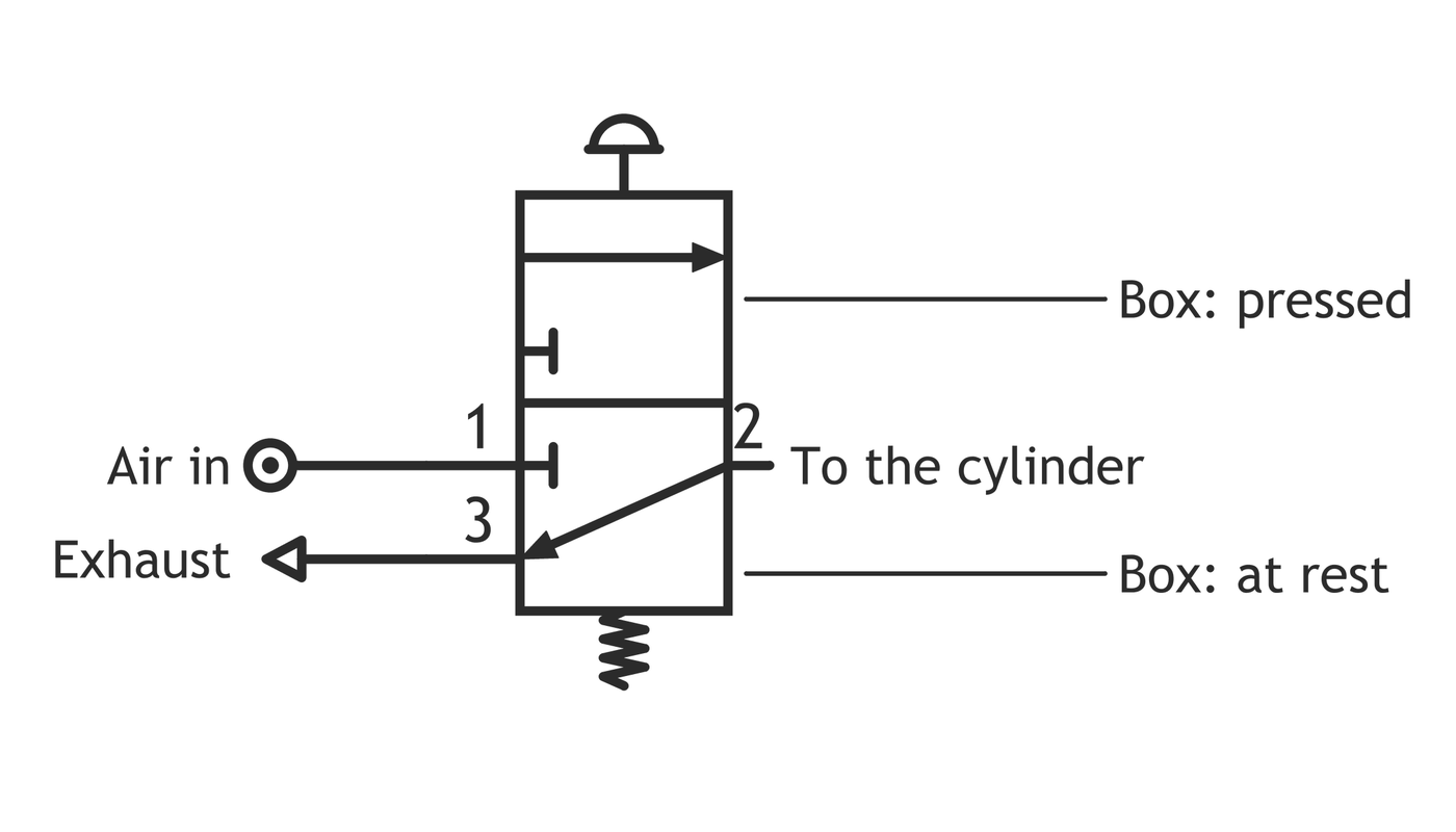
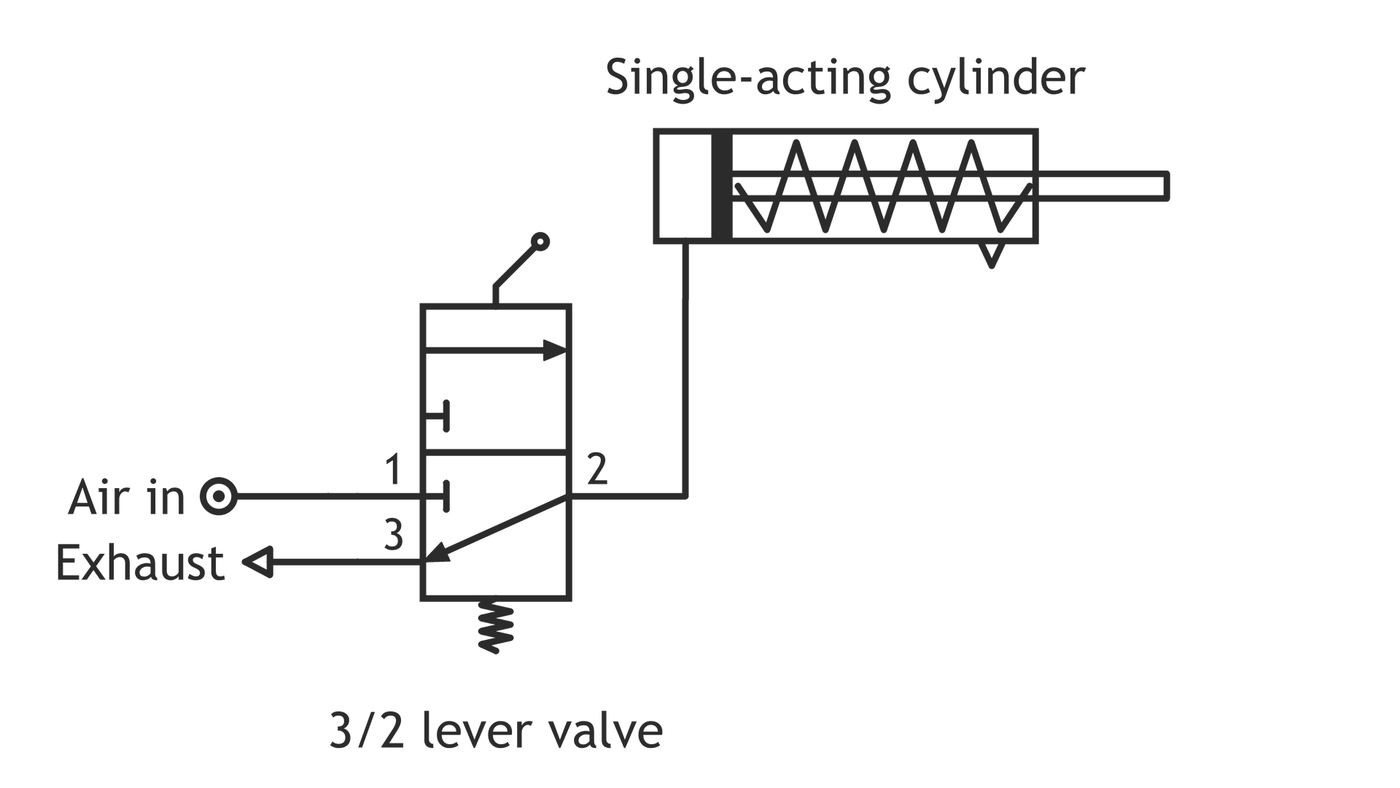
A valve symbol is drawn as boxes. Each box is one state of the valve. This valve has 2 boxes: pressed and at rest.
The ports join the bottom box, the one at rest.
| Port | What it does |
|---|---|
| 1 | Air in, from the air supply. |
| 2 | Air out, to the cylinder. |
| 3 | Exhaust: used air leaves here. |
3 ports and 2 states: we call it a 3/2 valve.
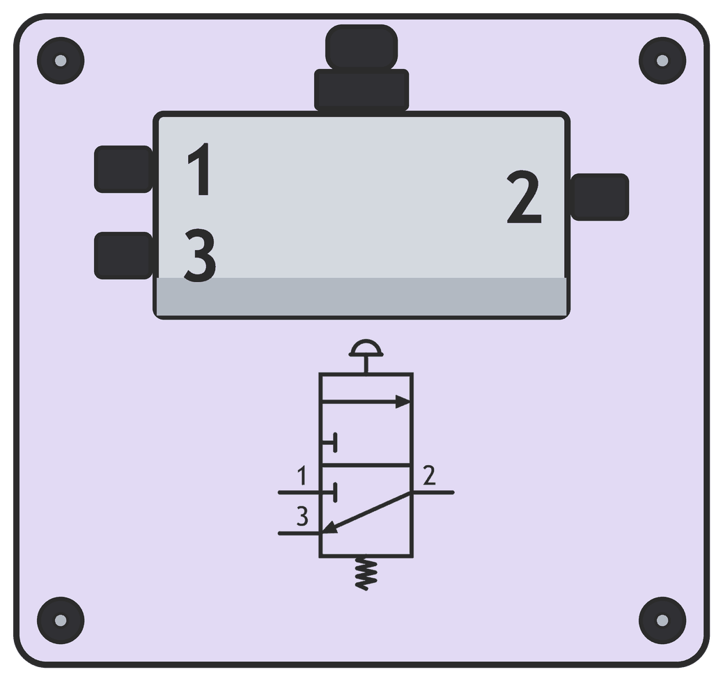
The real valve has the same three ports. Its symbol is printed on the plate, so you can always check which port is which.
1. State how many states a 3/2 valve has.
Answer
2. State which port the used air leaves from.
Answer
You can now…
- say what a box in a valve symbol means.
- name ports 1, 2 and 3.
Inside the boxes
Key words
- Arrow
- the path the air takes.
- T
- that port is blocked.
- Spring
- pushes the valve back.
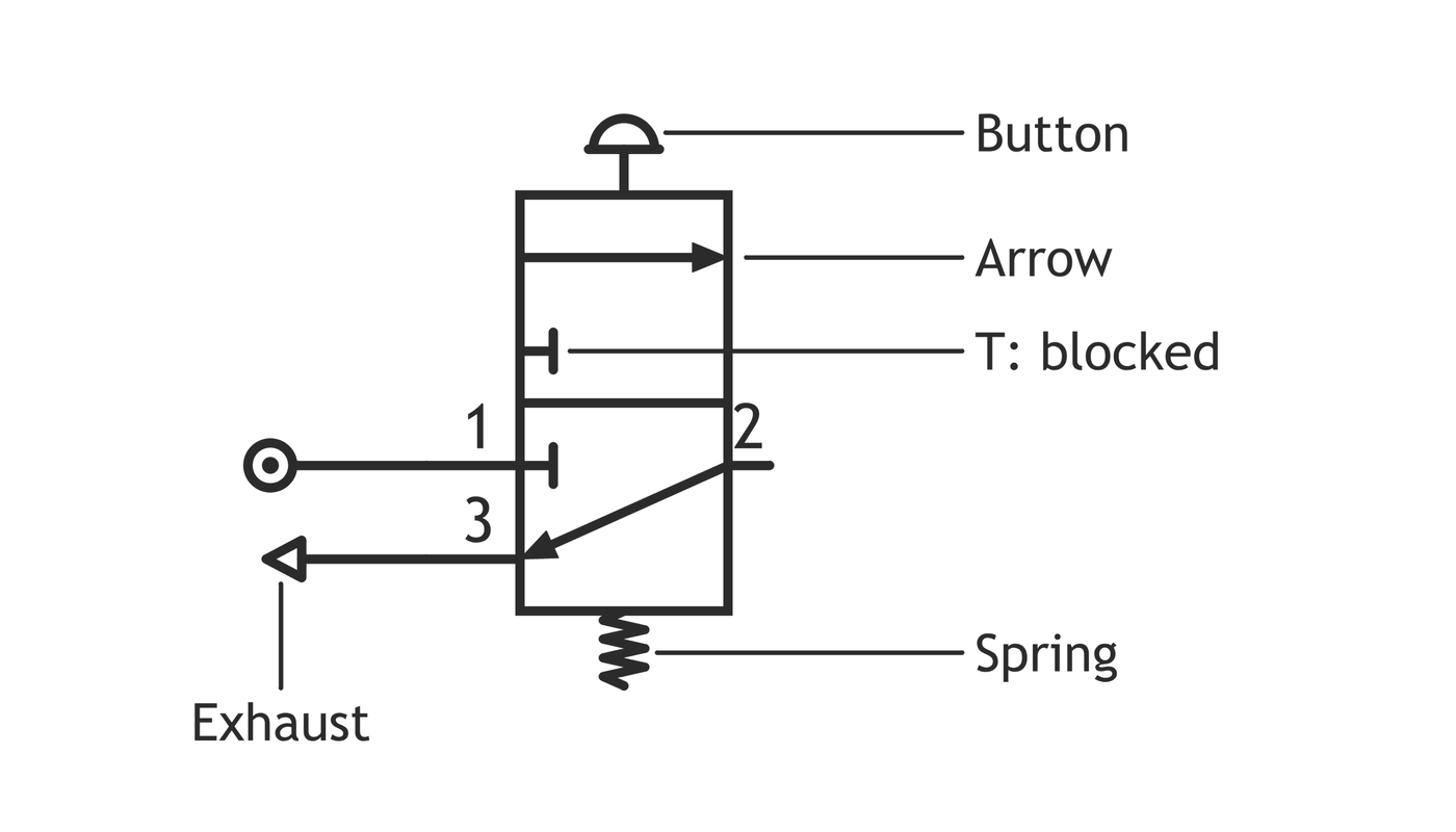
| Part | What it means |
|---|---|
| Arrow | The path the air takes. |
| T | That port is blocked. |
| Button | Push it to change state. |
| Spring | Pushes the valve back. |
Read the box that sits on the ports. At rest, the T sits on port 1, so the air supply is blocked. The arrow joins port 2 to port 3, so air can leave the cylinder.
1. State what a T in a box means.
Answer
2. State what pushes the valve back when you let go.
Answer
You can now…
- read the arrow and the T in a box.
- say what the button and the spring do.
Same valve, different push
Same boxes, same ports. Only the part on top changes: it is what pushes the valve.
Button
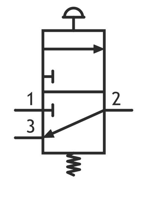
A finger pushes it.
Lever
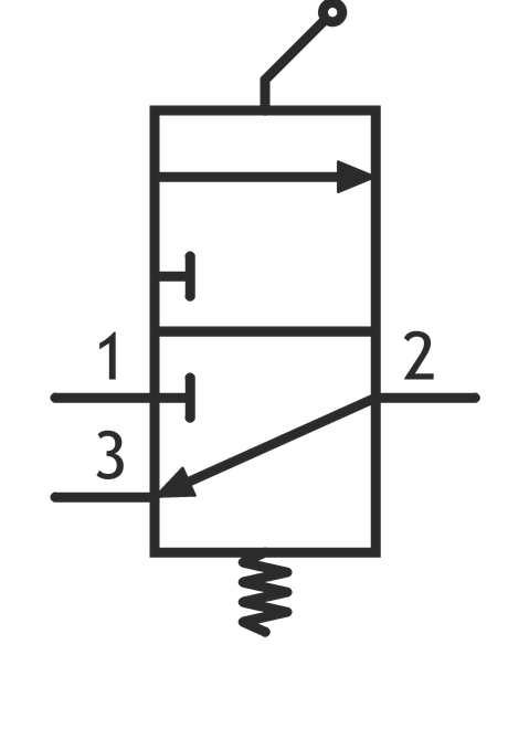
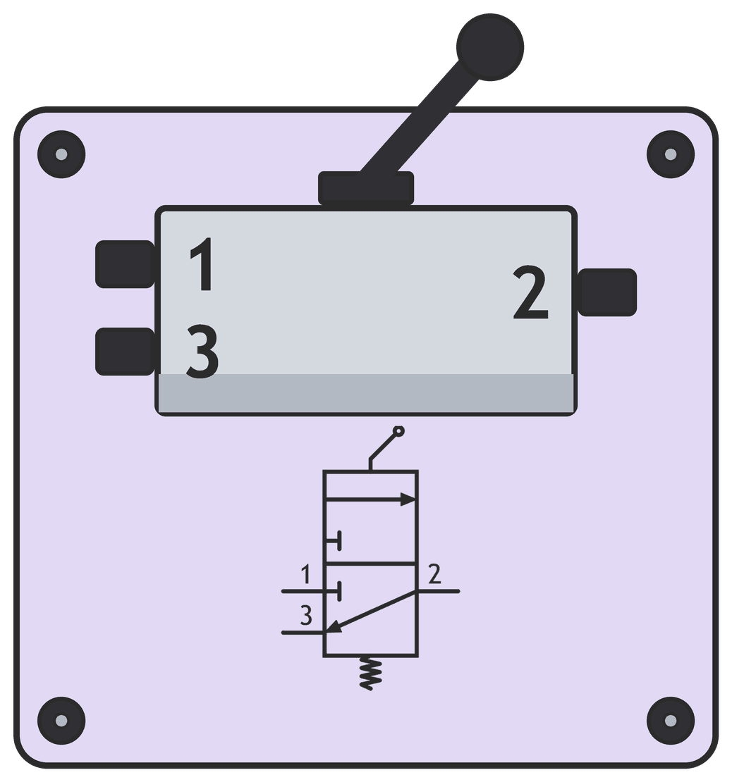
A hand moves it.
Roller
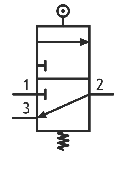
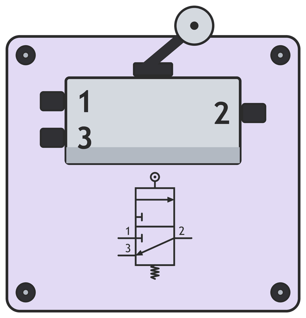
A train presses it as it goes past.
1. Name the valve a hand moves.
Answer
2. State what is the same on all three symbols.
Answer
You can now…
- tell a button, a lever and a roller valve apart.
Draw it full size
Key words
- Sliding rule
- the long rule across the board. Its top edge draws horizontal lines.
- Set square
- a triangle that sits on the rule to draw vertical lines and angles.
What to collect
- Drawing board
- Plain A3 paper
- 45° set square
- 60/30 set square
- Sharp pencil
- Eraser
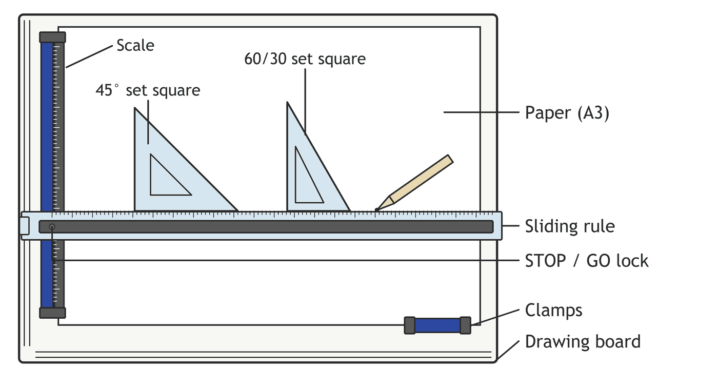
Using the board
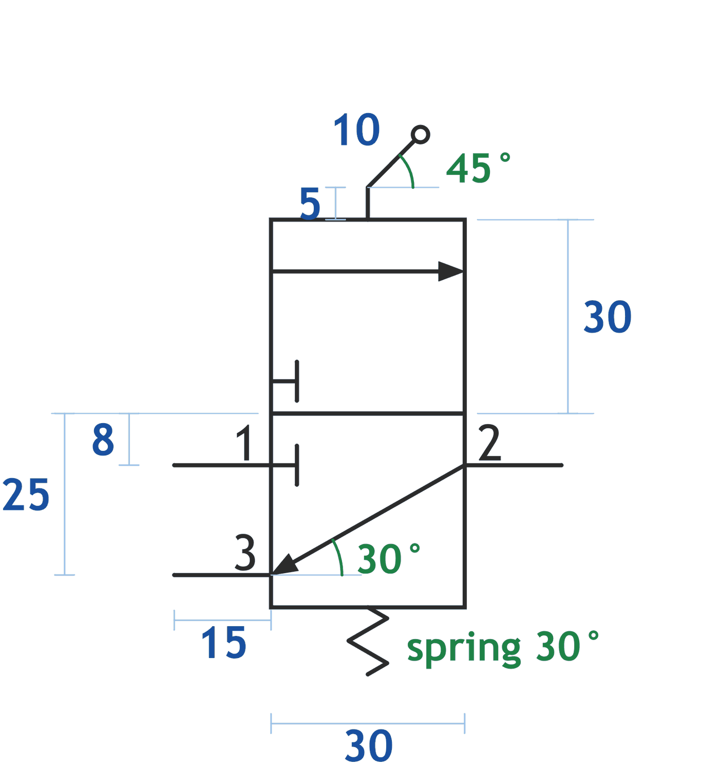
Draw the valve
Draw the rest
Every size
Sizes in mm. Small parts by eye. Pipes across or up only.
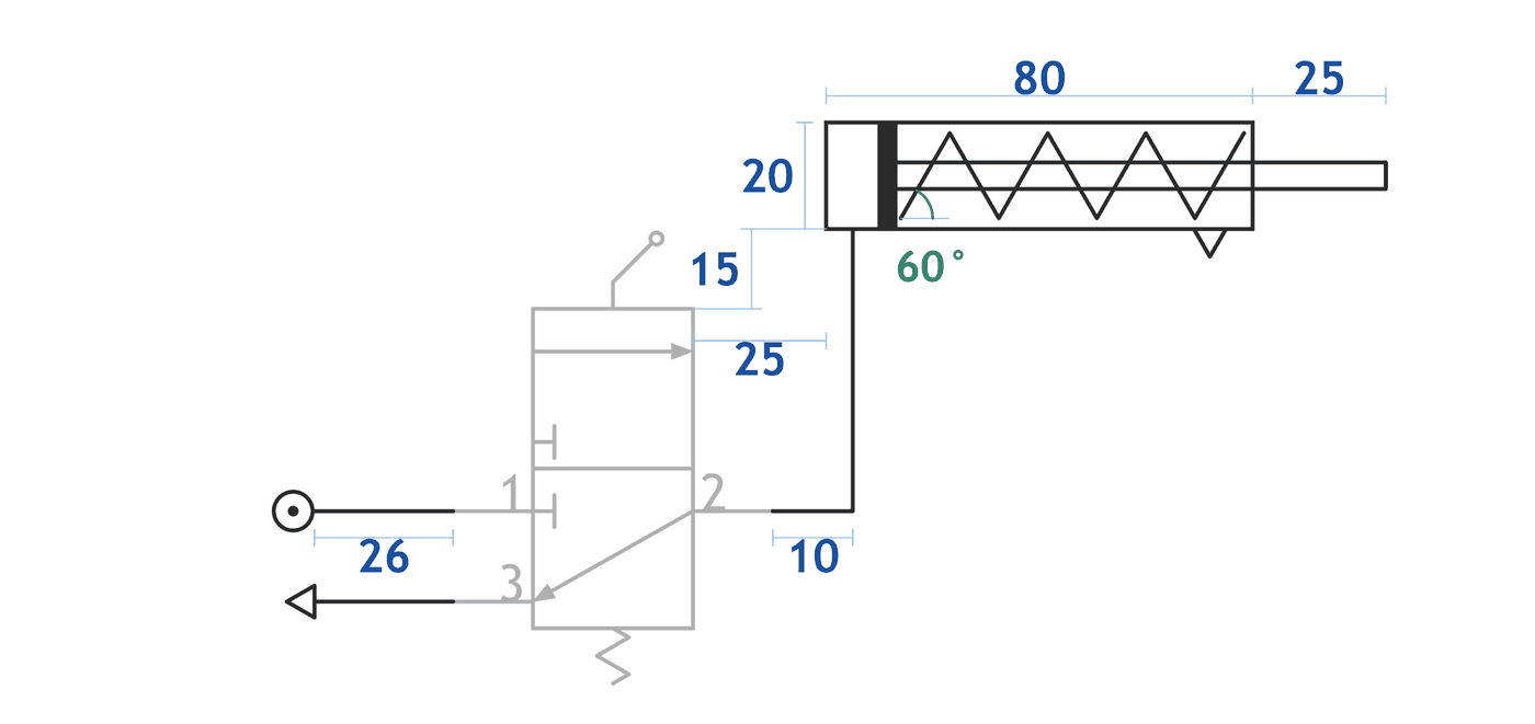
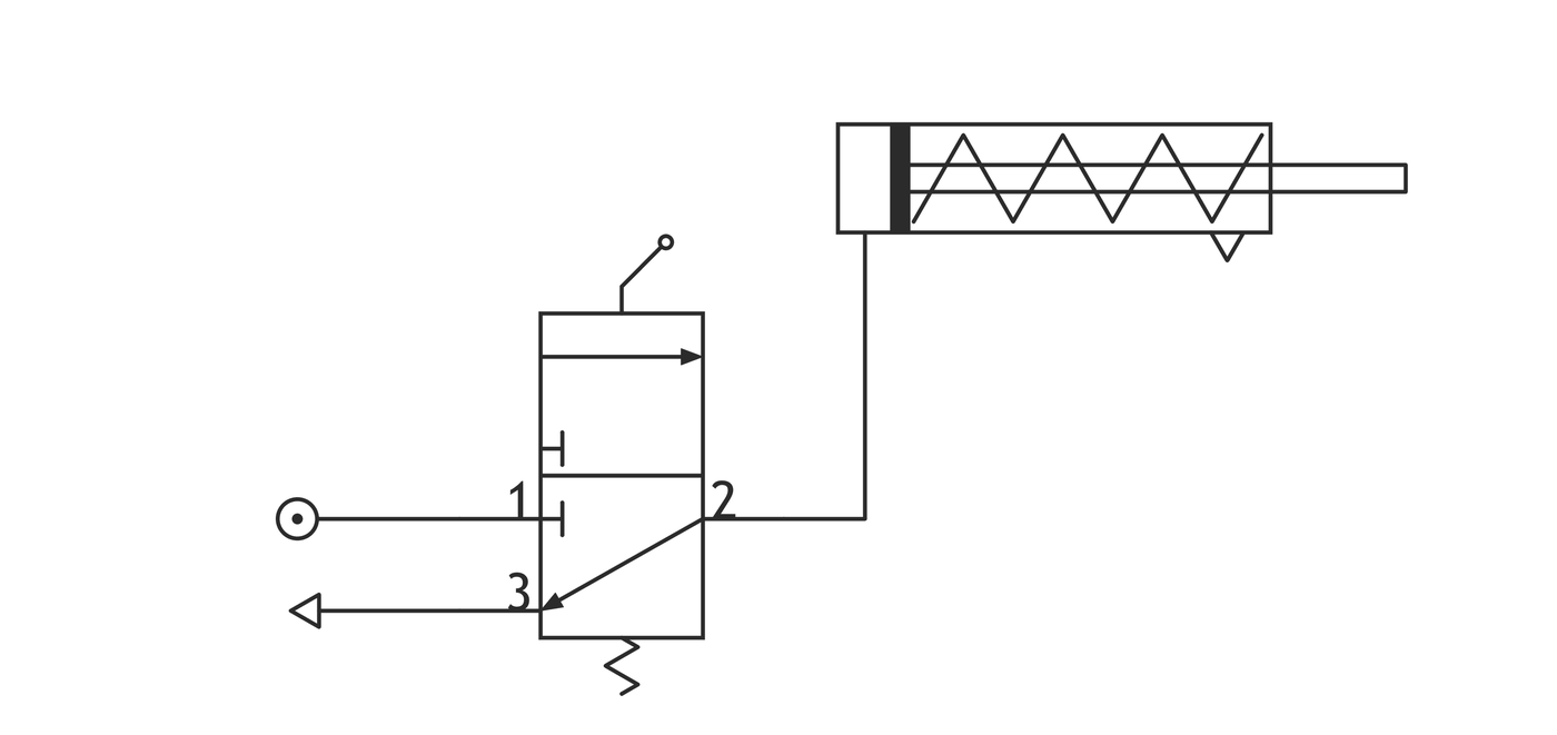
Check your drawing
| Sizes | the same as the guide |
|---|---|
| Ports | numbered 1, 2, 3 |
| Exhaust | on port 3 |
| Pipes | across or up only |
1. State which edge draws a horizontal line.
Answer
2. State the size of each box of the valve.
Answer
You can now…
- draw horizontal and vertical lines with the board.
- draw the gate circuit full size, with symbols.
Press and let go
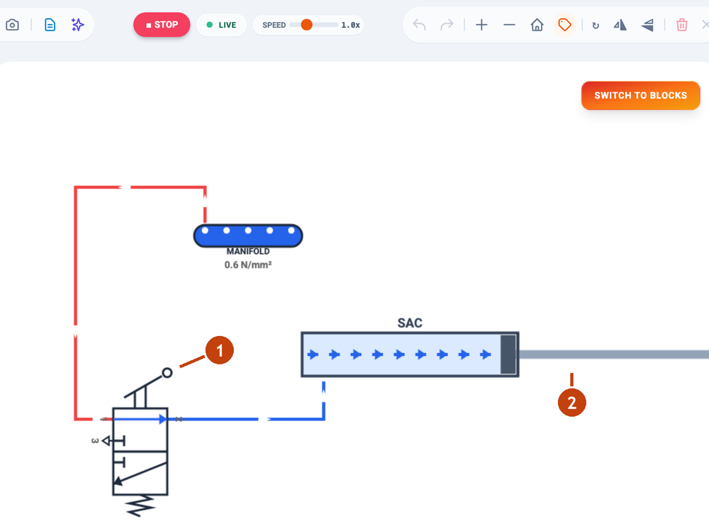
The lever gate you build. Tap the picture, or the button beside it, to move the air one step. Orange is air.
Spot the mistake. A pupil wrote: “When I let go, air goes into port 3 and pushes the rod back in.” Find the mistake. Fix it.
Answer
You can now…
- say what a 3/2 valve does when it is pressed.
- say what it does when it is let go.
The lever gate
The job
- When the lever is pushed, the rod moves out.
- When the lever is let go, the rod moves back in.
- The drawing shows every symbol and port.
What to collect
Builder and Safety: one set per team.
- Bench card 2
- Manifold (air supply)
- 3/2 lever valve
- Single-acting cylinder
- Tubing
- Goggles, one each
1. Simulate it
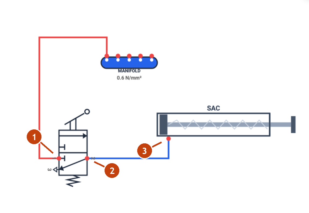
Tester and Recorder: start on the computer. Add the parts from bench card 2, join them up and press simulate. Push the lever, then let go.
Open NoPressureSim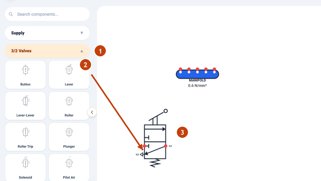
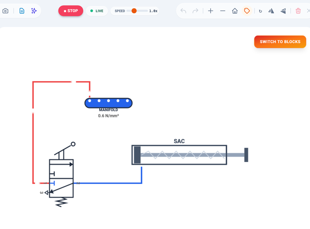
STOP. Air Permit before any air.
- Works in the simulation.
- Tubing checked.
- Regulator at 0.
- Goggles on.
Regulator at 0 to build. 1 to 2 bar to test. No permit, no air.
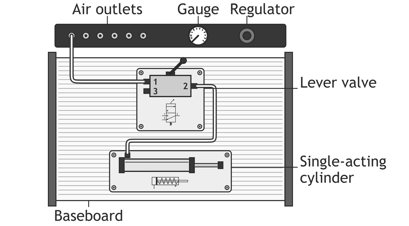
2. Build it: bench card 2
Builder and Safety: parts and bench card 2. Safety reads out each step.
3. Test it
Push, let go, listen. Then check each point of the job.
| Point | Met? | What did you find? |
|---|---|---|
| i Lever pushed: rod out | Yes / No | What pushed the rod out? |
| ii Lever let go: rod back in | Yes / No | What pulled the rod back? |
| iii Every symbol and port drawn | Yes / No | Let go: where did the air go? |
Check your test
- i Yes: air from the valve pushed the rod out.
- ii Yes: the cylinder's spring pulled the rod back.
- iii Let go: the air went out of the valve's exhaust, port 3.
Regulator back to 0 when you finish.
Port Patrol
Each 3/2 valve has one mistake, or none. Find it. Get 4 out of 5 on your first try to earn the Port Patrol badge.
Check your understanding
Pick an answer to see feedback on it. You can then try the others. Your score counts first tries only.
Fill the gaps
Push the button: both boxes slide . Port is now blocked. Let go: the pushes the boxes back. The used air leaves through the .
RAG self-check
Tap Red, Amber or Green for how sure you feel.
Booklet answers: Lesson 2
Try the task in your booklet first. Then tap to check.
Task 1: Now you, then your turn
- Question 1, line 2: The air goes into the cylinder and pushes the piston.
- Question 1, line 3: The rod moves out. The cylinder extends.
- Question 2: Roller pressed: the rod moves out (1). Train gone: the valve springs back and the rod goes in (1).
Task 2: Draw the gate circuit
Ports numbered 1, 2, 3. Ruler used. Exhaust on port 3.
Task 3: Simulate
Task 4: Air Permit and kit
Task 5: Questions
- Question 3: It has 3 ports and 2 states (1).
- Question 4: 0 bar (1).
Task 6: Key words
Picture glossary
Tap a part to see its symbol, the kit and its poster.
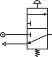
3/2 push-button valve
3 ports, 2 states. A finger pushes it.
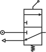
3/2 lever valve
The same valve. A hand moves the lever.
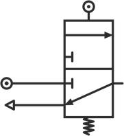
3/2 roller valve
The same valve. Something moving presses the roller.
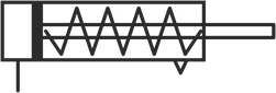
Single-acting cylinder
Air pushes the rod out. A spring pushes it back in.

Air supply
Where the air comes in. It joins port 1.

Exhaust
Where used air leaves. It is on port 3.
Sources & credits: the gate circuit and bench card 2 are adapted from the Matrix CP2080 Pneumatics Essentials Worksheet 1 (© Matrix Technology Solutions Limited). Kit drawings by R Stewart, from the Matrix CP2080 kit. Drawing board pictures drawn by R Stewart from photos of the class boards. Simulator screenshots: NoPressureSim by Peter Strain (NoStrainSims), free and open to all. Text, symbols, drawings and challenge by R Stewart. R Stewart - October 2026