Theory — Transistor Switching Circuits
Back to Electronics hub GlossaryA transistor switch lets a tiny input from a sensor switch a much bigger current on or off. It builds straight on the voltage divider.
The transistor switch
Key words
- Transistor switch
- a small input that switches a bigger current on.
- Base
- the transistor's control input; it turns on at about 0.7 V.
- Voltage divider
- two parts in series that set the base voltage from a sensor.
- Output device
- the lamp, LED or relay the transistor switches on.
You should be able to give a short "how it works" description of a transistor switch — and recognise its circuit diagram. All resistors are drawn the UK (BS) way, as a rectangle.
Transistor switch. A sensor — an LDR for light or a thermistor for temperature — sits in a voltage divider that feeds the transistor's base through a base resistor. When the base voltage rises to about 0.7 V, the transistor turns on and lets a much larger current flow through its output device (a lamp, LED or relay) — so a small input switches a bigger current. Swapping which arm of the divider holds the sensor sets whether it switches on for high or low light/temperature:
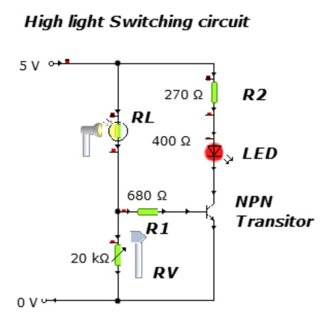
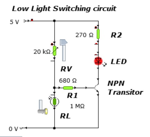
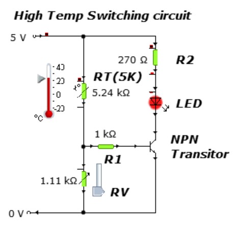
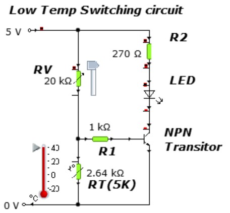
A sensor in a voltage divider feeds the transistor's .
When the voltage there reaches about V, the transistor turns .
This lets current flow through the (for example a relay or lamp).
See a full answer
An LDR-based transistor switch turns an LED on in the dark. Where in the voltage divider is the LDR placed, and what is the base voltage when the transistor switches on?
Answer
✅ You can now…
- describe a transistor switch: sensor → voltage divider → base → output device.
- explain how swapping the divider arm switches on for high or low light/temperature.
Transistor-switch simulator
Build the switch, drag the sensor's surroundings and watch the base voltage reach 0.7 V — the moment the transistor turns on. Then take the four design challenges to earn the 💡 Bright Spark badge.
Check your understanding
Answer the multiple-choice questions, then mark yourself with the RAG self-check.
RAG self-check
Tap Red / Amber / Green for how confident you feel.