
The Stripboard Planner is a blank board and a box of parts. Use it to plan your circuit before you solder it.
On this page
1. The screen
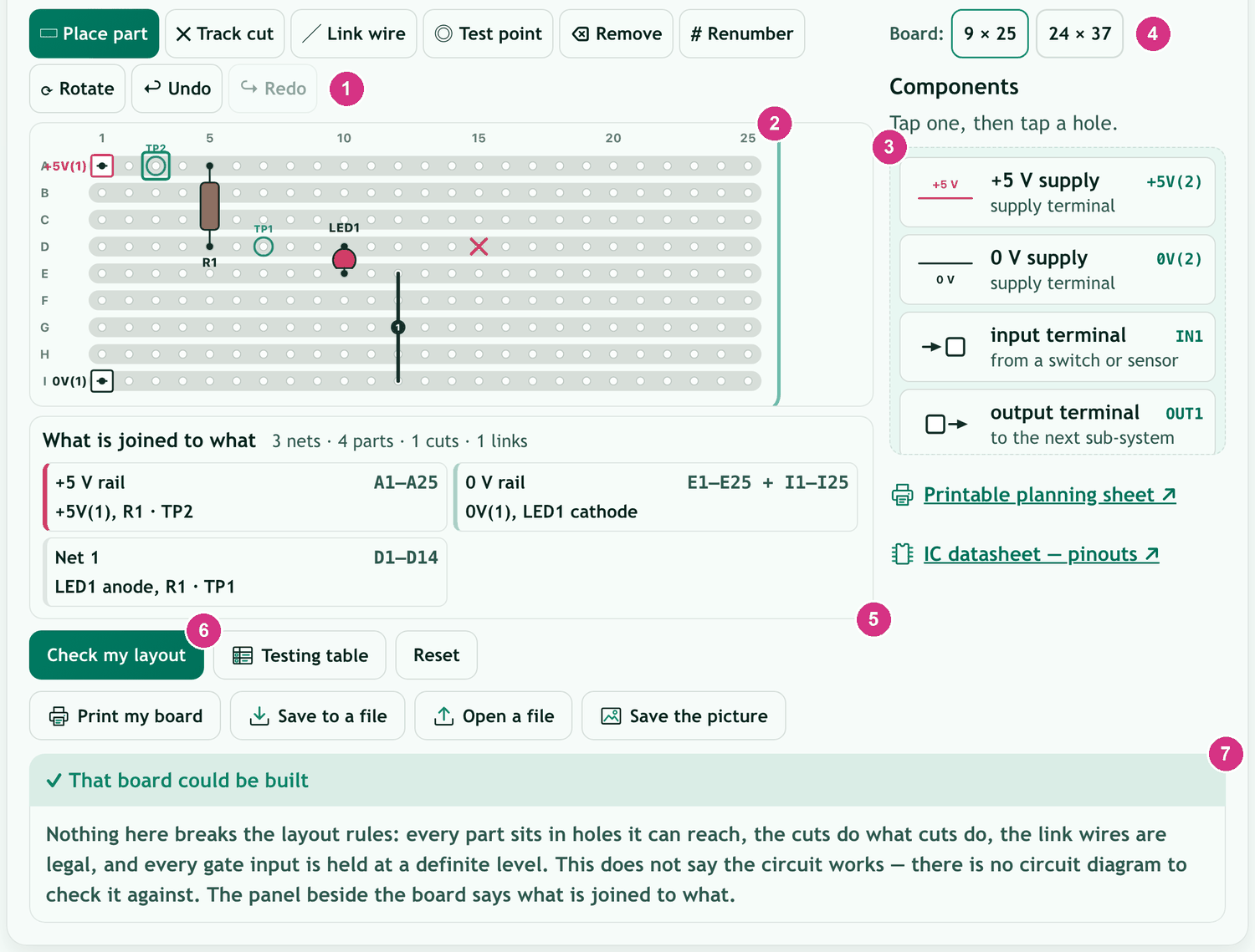
This is the whole planner. The numbers on the picture match this list.
- The tools. Pick a tool, then tap the board.
- The board. Each grey strip is one copper track.
- The parts list. Scroll it to find every part.
- Board: pick a small board (9 × 25) or a big one (24 × 37).
- What is joined to what. Every track, and what is on it.
- Check my layout. Checks your board.
- The message box. The planner talks to you here.
2. Place a part
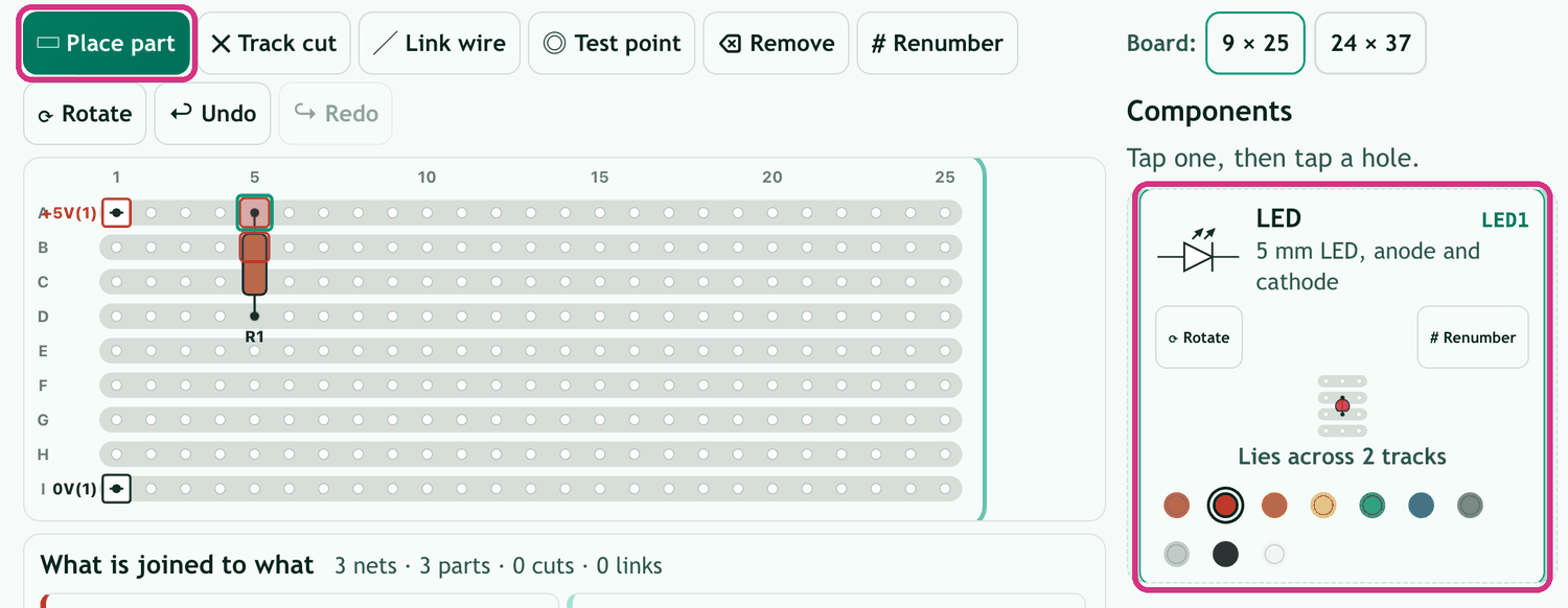
- Tap Place part.
- Tap a part in the list.
- Tap a hole on the board to put it down.
Tap Rotate to turn the part before you put it down.
To move a part, tap it on the board. It goes back in your hand. Then tap a new hole.
To take a part off, tap Remove, then tap the part.
3. Link wires and colours
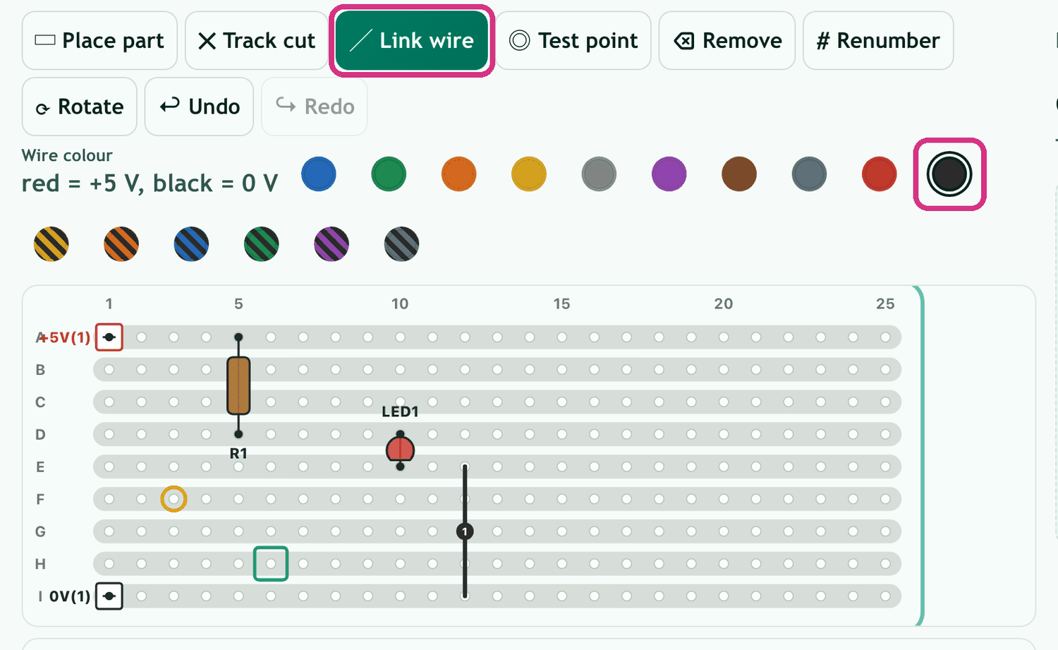
A link wire joins two tracks. Use red for +5 V and black for 0 V.
- Tap Link wire.
- Tap a colour.
- Tap one hole, then tap the other end.
The colour stays until you pick another one.
A link must run straight. It cannot lie on another wire or run under a part. If you try, the message box tells you why:
“Cannot run a link there. A link wire runs straight — along a row, or straight up and down a column…”
4. Track cuts
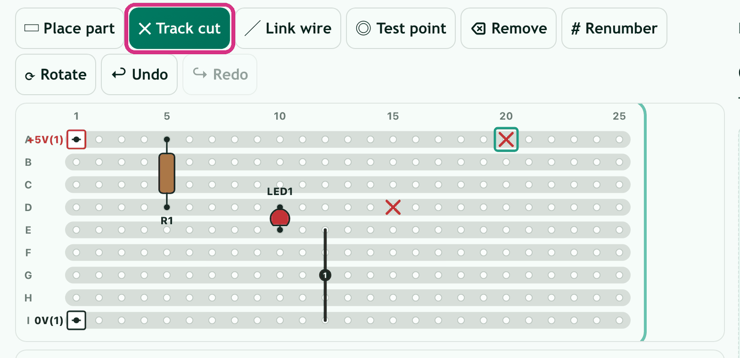
A track cut breaks the copper. The two sides are no longer joined. It shows as a red cross.
- Tap Track cut.
- Tap the hole where the copper must break.
- To take a cut away, tap the cross again.
You cannot cut a hole that has a leg soldered in it.
5. Test points and the testing table
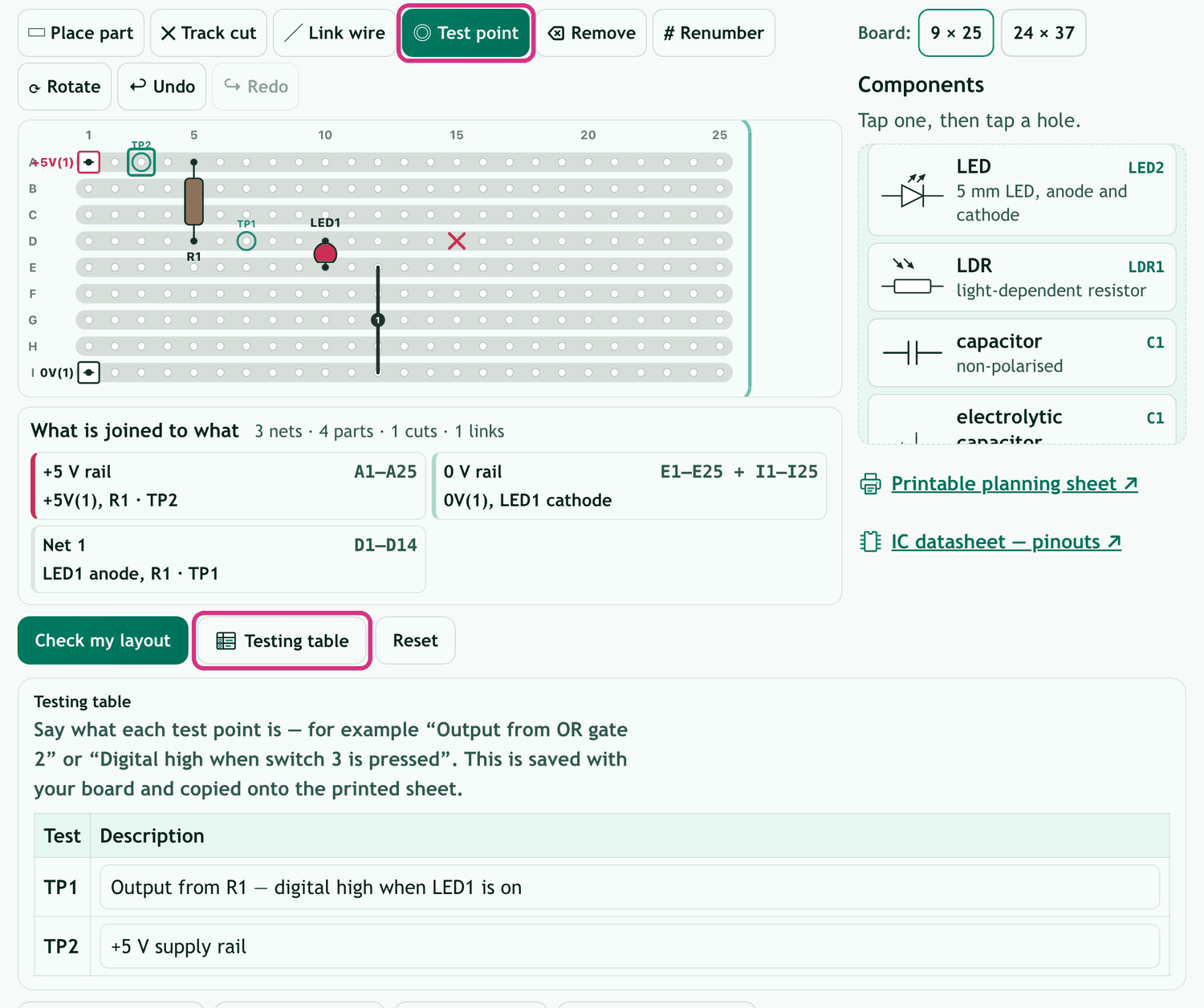
A test point is where you put the meter probe. They are numbered TP1, TP2 and so on.
- Tap Test point.
- Tap a hole. Tap it again to take the test point away.
- Tap Testing table. Say what each test point is.
For example: “Output from OR gate 2”, “Output from switch 3” or “Digital high when switch 3 is pressed”.
The table saves with your board. It prints with your board too.
6. Check my layout
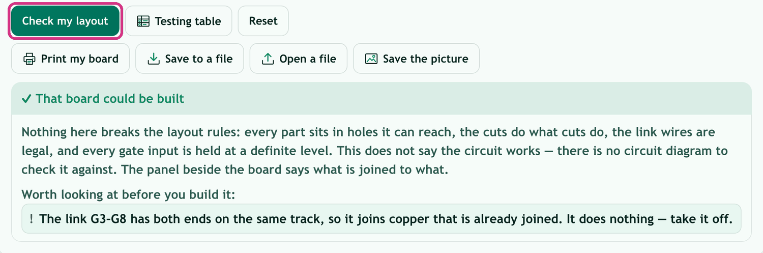
Tap Check my layout when you think your board is right. The answer shows in the message box.
- “3 things to fix” (or however many): the board cannot be built as it is. Each line says what is wrong.
- “✓ That board could be built”: nothing breaks the layout rules.
Some things are safe but not needed. They are listed under Also worth checking or Worth looking at before you build it. For example:
“The link G3–G8 has both ends on the same track, so it joins copper that is already joined. It does nothing — take it off.”
Check cannot see your circuit diagram. It checks the board could be built, not that the circuit does its job.
7. Undo and Redo
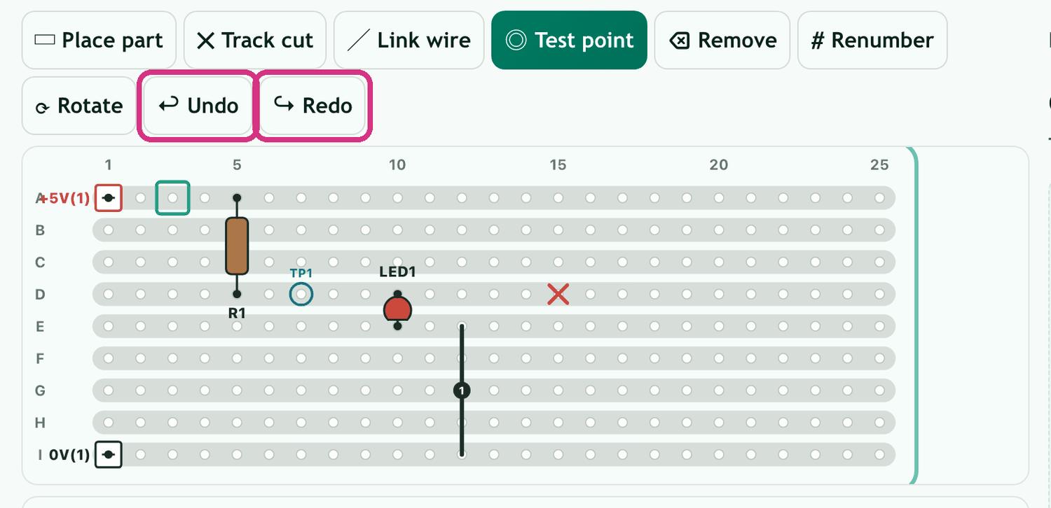
Undo takes back your last change. Redo puts it back.
Keys: Ctrl+Z to undo on Windows, or Cmd+Z on a Mac.
After you place a part, the first Undo puts it back in your hand. The second Undo takes it away.
Reset clears the board, and you can undo it. Changing the board size also clears the board, and that cannot be undone.
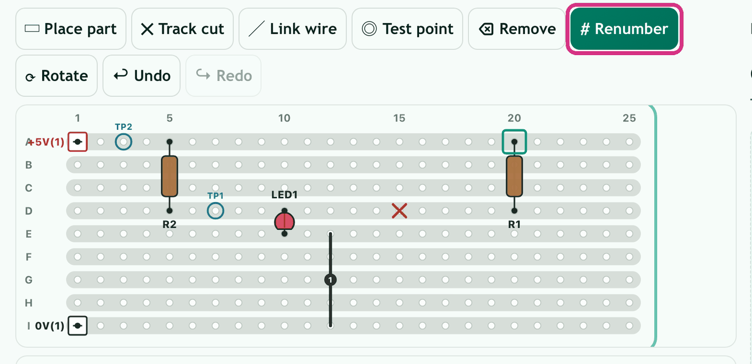
8. Renumber
- Tap Renumber.
- Tap a part on the board.
- Type a number from 1 to 99.
The letter stays the same: R stays R. Only the number changes.
If another part already has that number, the two parts swap numbers:
“R2 and R1 have swapped numbers.”
9. Save, open, picture and print
Your board saves itself in this browser. It will not follow you to another computer.
- Save to a file keeps a copy you can move.
- Open a file brings that copy back.
- Save the picture saves a picture of your board to put in a document.
- Print my board prints your board and your testing table.
Each one asks for a title first. Leave it blank to use the board’s own name.

10. If something goes wrong
- My link will not draw.
- Read the message box. It says why. A link must run straight, along a row or up and down a column. The first end stays picked, so tap a different second hole.
- My board has gone.
- Your board is kept in the browser you used. Open the planner on the same computer, in the same browser. If you saved a file, tap Open a file. If you have just pressed Reset, tap Undo.
- Check says nothing is on the board.
- Put a part down first. With no parts, Check says: “Nothing on the board yet — pick a part from the list and tap a hole to put it down.”
Sources & credits: screenshots of the Stripboard Planner. Full site credits are on the credits page. R Stewart - September 2026